|
|
1 2 V O L T T O W V E H I C L E T O T R A I L E R / T O A D W I R I N G
12 Volt DC Connectors
4 Pole Flat Connector
|
|
|
|
|
|
|
|
|
|
Uncovered Pin |
|
|
|
|
|
||
|
|
|
|
||
|
|
|
|
7 Pole Round Connector
|
(see back of plug) |
(Typical) |
TO |
|
|
|
|
|
|
|
|
|
|
|
|
|
|
|
|
|
|
|
|
|
|
|
|
|
|
|
|
![]()
125/250 V O L T "S H O
R E P O W E R" W I R I N G
(Click on any picture to enlarge)
NOTE: Before doing any work on 125 or 250 volt systems, make SURE you know what you are doing. Electrical panels can be very dangerous to work in. Never touch any of the main bus lugs in the panel as they can kill you! The best thing to do is to TURN OFF THE POWER TO THE PANEL before doing any modification or wiring. If you are not SURE of what you are doing, contact an electrical contractor for help.
For clarification, you will see the voltage associated with 30 amp RV service referred to as anything from 110 to 125 volts. For 50 amp service, you will see anything from "dual 125" to voltages from 220 to 250 volts. Don't let this confuse you. I will use the upper voltage to be consistent with the manufacturers drawings provided below.
125 Volt, 30 Amp AC Wiring
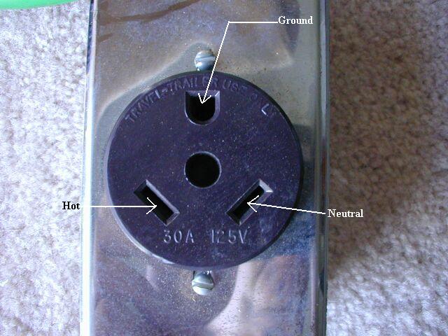
 30
amp RV service can deliver approximately 3,750 watts (125 volts
X 30 amps) to the RV. The 30 amp RV receptacle is a NEMA
TT-30R. The receptacle is usually marked "Travel Trailer Use
Only". The matching plug is a NEMA TT-30P. The receptacle
is wired with three wires from the breaker panel and requires a single,
dedicated 30 amp breaker.
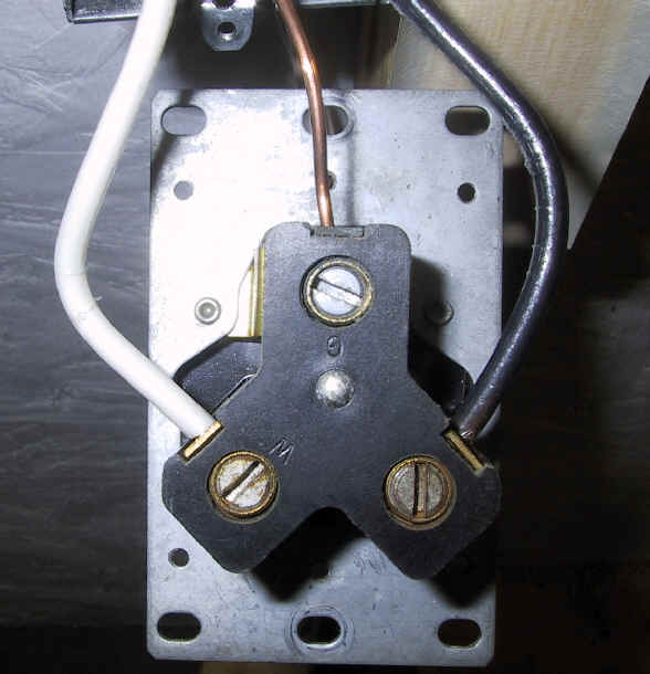
The three wires are one 125V (black), a ground (usually bare or green)
and a neutral (white). The terminals on the back of the
receptacle will be marked with G (and perhaps a green screw), W (and
perhaps a silver screw) and maybe B (and perhaps a brass screw) but in
many cases, the last terminal is not marked. The bare/green
ground wire goes to the screw that attaches to the metal frame of the
socket marked 'G'. The neutral goes to the side marked 'W' for white
and the black hot wire goes to the remaining screw
as shown. Before using the outlet, make sure you check the
polarity
with a tester.
30
amp RV service can deliver approximately 3,750 watts (125 volts
X 30 amps) to the RV. The 30 amp RV receptacle is a NEMA
TT-30R. The receptacle is usually marked "Travel Trailer Use
Only". The matching plug is a NEMA TT-30P. The receptacle
is wired with three wires from the breaker panel and requires a single,
dedicated 30 amp breaker.
The three wires are one 125V (black), a ground (usually bare or green)
and a neutral (white). The terminals on the back of the
receptacle will be marked with G (and perhaps a green screw), W (and
perhaps a silver screw) and maybe B (and perhaps a brass screw) but in
many cases, the last terminal is not marked. The bare/green
ground wire goes to the screw that attaches to the metal frame of the
socket marked 'G'. The neutral goes to the side marked 'W' for white
and the black hot wire goes to the remaining screw
as shown. Before using the outlet, make sure you check the
polarity
with a tester.
It is worthwhile noting that many modern electrical devices
(switches, duplex outlets, receptacles, etc.) now include color coded
screws. The normal color coding convention is green screw =
bare/green/ground, silver screw = white/neutral, and brass screw =
black/hot.
250 Volt, 50 Amp AC Wiring
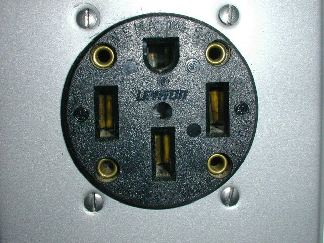 50 amp RV
service can deliver approximately 12,500 watts (125 volts X 50 amps X
2) to the RV. Some people believe that the 50 amp RV receptacle
is a "special" part. This is absolutely not true. In fact,
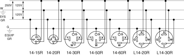
it is a commonly available 50 amp, 250 volt receptacle. Unlike
the 125 volt, 30 amp Travel Trailer receptacle, this one is used in
many different 250 volt applications. It carries part number
14-50R. The matching plug is a number 14-50P.
50 amp RV
service can deliver approximately 12,500 watts (125 volts X 50 amps X
2) to the RV. Some people believe that the 50 amp RV receptacle
is a "special" part. This is absolutely not true. In fact,
it is a commonly available 50 amp, 250 volt receptacle. Unlike
the 125 volt, 30 amp Travel Trailer receptacle, this one is used in
many different 250 volt applications. It carries part number
14-50R. The matching plug is a number 14-50P.
There is a lot of misunderstanding about how MOST 50 Amp RV's are wired. Some of the larger bus type diesel pushers are all electric and in fact, do have 250 volt appliances in them. In that case, both sides of the 50 amp circuit are used to power those devices (just like your home) and those coaches MUST have 50 amp, 250V service in order to run things like the 250V stove, AC and the electric water heater. In the case of the rest of the 50 amp RV's, 250 volts is still supplied to the coach just like your home electrical service but typically one side of the line is used for all the 125 volt appliances except the rear AC and the other side is used for the rear AC only. The service coming into the RV is still 50 amp, 250 volts. Please note that all of the 50 amp RV's (at least in the US) use the SAME receptacle wired in the SAME way. If they didn't, they couldn't all plug into the same outlets at the RV park.
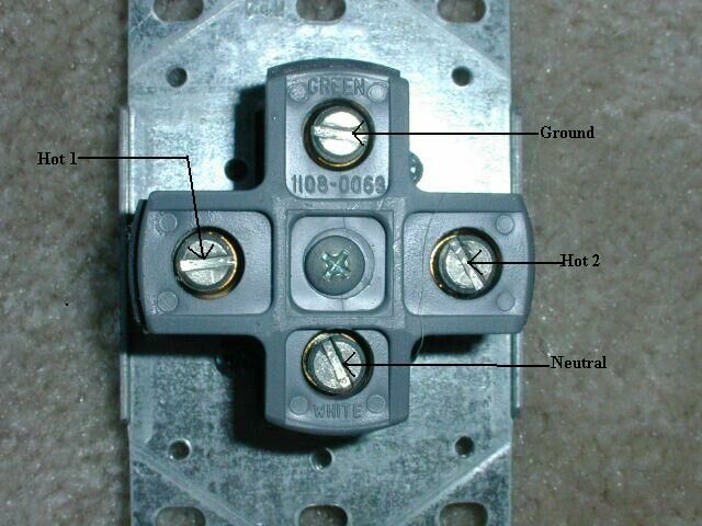
 On the back of the 250V receptacle, there will
be
four terminals labeled W (or white), G (or green), and possibly X and
Y. (see picture)
The wires
going to terminals X & Y on the receptacle are the hot wires and
are
interchangeable, the hot wires from the panel are typically red and
black.
The neutral W, (white) and the bare (or green) ground wire G, MUST be
on
their designated connections. The bare/green wire should also be
grounded
to the electrical box the receptacle is mounted in (if metallic).
Most
14-50R receptacles provide a strap from the ground terminal to the
mounting
plate of the receptacle itself. (see picture) Be sure
to use the properly rated electrical box
designed to be used with your receptacle. Make sure you run large
enough
wire to handle the load over the distance you are running. Here
is
a page from the Leviton catalog
that shows the wiring schematically.
On the back of the 250V receptacle, there will
be
four terminals labeled W (or white), G (or green), and possibly X and
Y. (see picture)
The wires
going to terminals X & Y on the receptacle are the hot wires and
are
interchangeable, the hot wires from the panel are typically red and
black.
The neutral W, (white) and the bare (or green) ground wire G, MUST be
on
their designated connections. The bare/green wire should also be
grounded
to the electrical box the receptacle is mounted in (if metallic).
Most
14-50R receptacles provide a strap from the ground terminal to the
mounting
plate of the receptacle itself. (see picture) Be sure
to use the properly rated electrical box
designed to be used with your receptacle. Make sure you run large
enough
wire to handle the load over the distance you are running. Here
is
a page from the Leviton catalog
that shows the wiring schematically.
125/250V 3-Pole 4Wire Grounding
NOTE: The two 125V circuits are additive when you connect across the two hot legs. Therefore the neutral wire must carry the difference current between the two circuits. That is to say, if both circuits are delivering 30 amps, the neutral wire is carrying zero amps. On the other hand, if one circuit is delivering 30 amps and the other is delivering nothing, the neutral wire is carrying 30 amps. It is important to make sure the neutral wire is large enough for its load as well. Under worst case circumstances, it could be carrying up to 50 amps just like either of the hot legs. Make sure your electrician knows the outlet will be used with an RV and the load might well be unbalanced. Thus the reason for the caution on the neutral wire size. Please remember that this applies to ALL wire associated with RV wiring whether it is the wiring from the breaker(s) to the socket or receptacle, the umbilical from the RV to the socket or the wiring inside the RV. Please make sure that all wiring is sized to handle the required current. Again, if you are not sure of what you are doing, consult a licensed electrician for help.
 The breaker for
this service must be a dual (double) 50 amp 250V breaker. A dual
250V breaker means that the breaker must be of the type that actually
connects to both bus bars in the panel, every other bus lug in the
panel is on the opposite leg of the incoming power line. If you
were to measure the voltage between opposite lugs in the panel, you
would measure 250V,
if you were to measure between either bus lug and a ground or neutral
bus,
you would measure 125V. If you ask your local building or
electrical
supply depot for a dual 50 amp breaker for use in a 250V dryer or range
circuit for your model/make breaker panel, they will be able to pick
out
the correct breaker for you. Please note that electrical panels
are
very dangerous to work in. Never touch any of the main bus lugs in the
panel,
they can kill! Turn off all power to the panel while connecting
the
new breaker. Also note that a 250V dual breaker has both breakers
bridged or ganged together so that if one of the dual breakers trips it
will also trip the other side. Although the most common dual
breakers
have one toggle for each side of the line, some 250V breakers have only
one toggle tab, and are bridged internally.
The breaker for
this service must be a dual (double) 50 amp 250V breaker. A dual
250V breaker means that the breaker must be of the type that actually
connects to both bus bars in the panel, every other bus lug in the
panel is on the opposite leg of the incoming power line. If you
were to measure the voltage between opposite lugs in the panel, you
would measure 250V,
if you were to measure between either bus lug and a ground or neutral
bus,
you would measure 125V. If you ask your local building or
electrical
supply depot for a dual 50 amp breaker for use in a 250V dryer or range
circuit for your model/make breaker panel, they will be able to pick
out
the correct breaker for you. Please note that electrical panels
are
very dangerous to work in. Never touch any of the main bus lugs in the
panel,
they can kill! Turn off all power to the panel while connecting
the
new breaker. Also note that a 250V dual breaker has both breakers
bridged or ganged together so that if one of the dual breakers trips it
will also trip the other side. Although the most common dual
breakers
have one toggle for each side of the line, some 250V breakers have only
one toggle tab, and are bridged internally.
The ground bus in the breaker panel is a terminal block with many small holes where the bare ground (or green) wire can be connected and tightened into place with a screw. This bus is electrically connected directly to the metal enclosure of the panel.
The neutral bus in the breaker panel is also a terminal block with many small holes where the white neutral wire can be connected and tightened into place with a screw. However, this bus is mounted so that it is NOT electrically connected to the metal enclosure. It is very important that the neutral (white) NOT be connected to the breaker box. For safety, the neutral and ground are only tied together at the meter panel on the house.
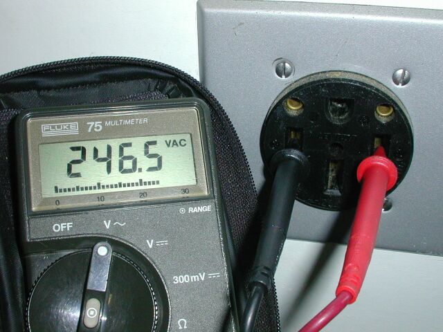
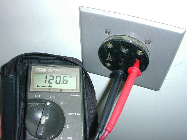 After completing all the wiring and closing up
the
boxes, it is a good idea to test the outlet for proper wiring with a
voltmeter or appropriate circuit tester. You should measure 125V
from either vertical blade
(check them both) on the side of the socket to either the neutral slot
on
the bottom or the ground contact on the top as well as to the box the
socket is mounted in if it is a metal box. You should measure
250V from one
side blade to the other side blade.
After completing all the wiring and closing up
the
boxes, it is a good idea to test the outlet for proper wiring with a
voltmeter or appropriate circuit tester. You should measure 125V
from either vertical blade
(check them both) on the side of the socket to either the neutral slot
on
the bottom or the ground contact on the top as well as to the box the
socket is mounted in if it is a metal box. You should measure
250V from one
side blade to the other side blade.
My WebCounter says you are visitor number since
September 10, 2002.
Get your free web page hit counter at 
E-mail me at ultrasport(REMOVE)@mail.com
© Copyright 2002, 2003, 2004 Steve Das